


-
Multichannel high-precision multimeter ElMetro-Kelvin

Multichannel high-precision multimeter ElMetro-Kelvin is intended for measuring electric signals parameters (voltage, current and resistance), measuring output signals of thermo-electric converters and resistance temperature detectors as well as unified current signals 0-5 mA and 4-20 mA.
Multimeters are applied as multichannel reference measuring instrument which is supplied as part of automated verification system for temperature sensors: thermo-electric converters according to GOST R 8.585-2001, resistance temperature detectors according to GOST 6651-94 and GOST 6651-2009, DIN 43760 and sensors with unified output signals 0-5 mA, 4-20 mA according to GOST 26.011-80. One of the channels should be connected to the reference temperature converter, whereas other are connected to verified transducers. Multimeter also enables to verify sets of coupled resistance temperature detectors for heat meters.
Multimeter is operated as a multichannel reference measuring instrument in automated verification system for sensors of other physical quantities with unified output signal 0-5 mA and 4-20 mA.
Multimeter could be used in laboratories as operable or reference multichannel measuring instrument for verification, calibration and adjustment of various measuring and measuring & computing complexes.
Multimeter could be applied for certification of thermostats temperature patterns and technological equipment such as drying ovens, thermal chambers, furnaces and autoclaves.
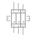
Description of multimeter model code is provided below:

Technical characteristics of multimeter ElMetro-Kelvin:
Multimeter is equipped with 8 independent analog inputs each of which could be freely reconfigured to carry out following measurement:
- Direct current load measurement;
- DC voltage measurement;
- Measurement of resistance to DC current.
Measurement ranges and limit of permissible main error for a relevant function of the multimeter correspond to the values listed in Table 1:
Function Range Least significant digit value Limits of permissible main error within temperature range from 15 to 35 °C, ± 1 2 3 4 Direct current load measurement ± (0-25) mA 0.0001 mA 65·10-6·X+0.25 mkA DC voltage measurement ± (0-200) mV
± (0-1.1) V0.1 mkV
1 mkV50·10-6·X+2 mkV
50·10-6·X+10 mkVMeasurement of resistance to direct current 0-400 Ohm
400-2000 Ohm0.001 Ohm
0.001 Ohm25·10-6·X+0.0035 Ohm
25·10-6·X+0.02 OhmNote:
X - value of measured parameter
Multimeter measures signals of thermal couples with NSC in accordance to GOST R 8.585 – 2001 with possible thermal EMF compensation of cold junction. TC types, limits of permissible main error and measurement ranges of TC signals correspond to the values listed in Table 2:
Thermocouple type Measurement range for output signals, °C Limit of premissible main error in relation to nominal static characteristics (NSC), ±(°C)* Least signififcan digit value, °C R from 0 to +200 0.4 0.01 from 200 to +1600 0.2 S from 0 to +200 0.4 from 200 to +1600 0.2 B from 600 to +1000 0.4 from 1000 to +1700 0.2 N from -200 to +1300 0.2 K from -200 to +1370 0.2 T from -200 to +400 0.2 J from -200 to +1200 0.2 E from -200 to +1000 0.15 L from -200 to +800 0.2 A-1: A-2; A-3 from 10 to +2500 0.5 Note:
* - Regardless to permissible absolute error for thermal EMF compensation of cold justion (±0.3 °C)
Multimeter measures signals of resistance temperature detectors (TSP, TCM, TCN) with NSC in accordance to GOST 6651-94 and GOST 6651-2009. Types of resistance temperature detectors (RTD), limits of permissible main error and measurement ranges of RTD signals correspond to the values listed in Table 3.
RTD type W100 Measured temperature range, °C Limit of permissible main error in relation to nominal static charateristics (NSC), ±(°C)* Least significant digit value, ºC 50P 1.3910 from -199 to +849 ± (0.02+0.000025*t) 100P ± (0.015+0.000025*t) 200P for temperatures below 260°C
± (0.015+0.000025*t)
for temperatures 260°C and above
± (0.03+0.000025*t)500P 1.3910 from -195 to +849 ± (0.015+0.000025*t) 1000P from -195 to +250 ± (0.015+0.000025*t) Pt50 1.3850 from -195 to +845 ± (0.02+0.000025*t) Pt100 ± (0.015+0.000025*t) Pt200 for temperatures below 260°C
± (0.015+0.000025*t)
for temperatures 260°C and above
± (0.03+0.000025*t)Pt500 ± (0.015+0.000025*t) Pt1000 from -195 to +250 ± (0.015+0.000025*t) 50M 1.4280 from -179 to +200 ± (0.02+0.000025*t) 53M ± (0.02+0.000025*t) 100M ± (0.015+0.000025*t) Cu50 1.4260 from -49 to +199 ± (0.02+0.000025*t) Cu100 ± (0.015+0.000025*t) 100N 1.6170 from -59 to +179 ± (0.015+0.000025*t) Ni-100 ± (0.015+0.000025*t) Note:
t - measured value in Celsius degrees
All channels are connected to a unified internal measuring circuit via input analog multiplexer. Identity of the channels metrological estimated according to resistance measurement at 400 and 2000 Ohm complies with following condition: difference in measurement results of the channels does not exceed half of permissible error in a relevant point.
Input resistance of the channels is:
- not more than 100 Ohm – for current measurement;
- not less than 40 MOhm - for voltage measurement.
Excitation current of resistance measurement is:
- in the range of 0…400 Ohm (1.09± 0.01) mA;
- in the range of 400…2000 Ohm (0.495± 0.005) mA.
Multimeter is equipped with two built-in power supply sources +24 V galvanically isolated from each other and the rest of the circuit. They provide power supply of sensors with unified output current signal during verification process, besides one of the sources connected to an active measuring channel is low-noise, whereas another one which ensures heating simultaneously with power supply of other sensors is more powerful. By means of internal communication the low-noise source sequentially connects to output terminals of all channels which are configured to measure unified current signals.
Operation mode setup-time after multimeter start-up does not exceed 30 min.
Multimeter provides indication of:
- electric signals – 7 significant digits;
- temperature – 7 significant digits.
Multimeter user interface executes the following functions:
- selection of measuring channel number;
- selection of a measured parameter;
- selection of measured parameter ranges;
- operations with memory: record, export, refresh and cleaning;
- reset of measurement results;
- serial port settings;
- adjustment of the screen contrast;
- calibration of the device cyclic error.
Multimeter should be powered via three-wire connection by a single-phase network with (220±22) V AC voltage and (50±1) Hz frequency.
Electric isolation:
- between any of power supply terminals (except for the middle one) and device housing withstands 1500 V AC voltage (rms value) within 1 min under frequency from 45 to 65 Hz;
- between short-circuited terminals of any analog input and device housing withstands 100 V AC voltage (rms value) within 1 min under frequency from 45 to 65 Hz.
Electric resistance of the multimeter isolation is not less than 20 MOhm under ambient temperature 23±5 ºС and relative humidity 80 %. Test voltage is 500 V DC.
Multimeter ensures galvanic isolation of the channels (excludes interchannel current) under interchannel voltage less than 10 V.
Multimeter provides archiving of analog signals measurement results.
Multimeter enables to prepare verification protocols.
Multimeter is equipped with a built-in RS-232 interface and service software for PC which makes automation of verification process possible.
Ambient temperature range: from +5 to +50 °С.
Multimeter Ingress Protection Rating corresponds to IP40 according to GOST 14254.
Overall dimensions of the multimeter correspond to the dimensions shown in Pic.2.
Multimeter weight: not more than 3 kg.
Mean time between failures: not less than 30000 h.
Average life-time: not less than 8 years.
Verification interval: 1 year. Verification could be carried out by the manufacturer or at Rostechregulation regional offices.
Guarantee commitment: 12 months from the date of putting into operation, but not more than 18 months from the shipping date from manufacturer factory.
Multichannel high-precision multimeter ElMetro-Kelvin is listed in National register of measuring instruments no. 47848-11.
Supply package of multimeter ElMetro-Kelvin:
- standard supply package of multimeter ElMetro-Kelvin includes: multimeter ElMetro-Kelvin (1 pc.), network cable with a slot for connection to a device (1 pc.), KTP type cable for connection of thermal couples (with a built-in thermal probe for thermal EMF compensation of cold junction) (2 pcs. + options), KTS type cable for connection of resistance temperature detectors (2 pcs. + options), KTI type cable for connection of sensors with unified output current signal (4 pcs. + options), null-modem cable or USB interface adapter for PC (1 pc.), product certificate (1 pc.), manual instruction (1 pc.), verification procedure description (1 pc.).
- additional supply package of multimeter ElMetro-Kelvin includes: KTU type cable for connection of sensors with output signal in the form of voltage (quantity is defined in an order).
Device description and operation of multimeter ElMetro-Kelvin:
Multimeter is designed as a desktop type (view Pic. 1. Structure of multimeter ElMetro-Kelvin). The front side panel includes:
- LCD (1) intended for display of measured values: voltage, current, resistance or temperature as well as operation modes, contrast and etc.
- touch-sensitive capacitive keyboard (2) which enables to select device operation modes and input parameters values.
Slots for connecting verified devices and 220 V network, a power button and communication with PC via RS-232 are placed at the back side of multimeter.

Multimeter consists of:
- processor and keyboard boards;
- one measurement board;
- four double-channel boards;
- power supply source of multimeter;
- two independent +24 V power supply source for external sensors.
Measured electric signals get to the multiplexer input via protective circuits, which prevent electronic circuit from overloads, and then follow to ADC input which converts measured electric signal into a digital code that is further processed by a measurement board microprocessor. Reference-voltage source (RVS), internal resistance references and temperature sensor which is applied for thermal compensation of RVS and measurement circuits provide high precision of measurement. This way measurement error dependence on ambient temperature is minimum.
Functions of multimeter control and measurement results processing are executed by a processor board microprocessor. Moreover, this component is responsible for data output in the screen and keyboard input.
Multimeter is powered via three-wire connection by 220 V AC network.
Adapter which is plugged into RS-232 slot at the multimeter housing provides interaction with PC.
Automatic verification of sensors is available.
Multimeter stores verification results and relevant configuration of multimeter. Files management is available in «Archive» menu. Operator can open or delete a file as well as to completely delete all files.


Customers’ feedbacks:
To view customers’ feedbacks on products of ElMetro company, please, follow the link.
To make enquiry and get a commercial offer on multichannel high-precision multimeters ElMetro‑Kelvin of the Russian manufacturer ElMetro company, please, send us product order code (view manual instruction) to e-mail: info@elmetro.ru or contact us via tel.: +7 (351) 220-06-01. To discuss technical questions, please, refer to technical support tel.: +7 (351) 220-06-03.
ARM-Kelvin is a software designed for multichannel high-precision multimeter ElMetro-Kelvin and intended to automate processing of verification results of temperature measuring instruments, create verification protocol templates, generate verification protocols and save verification information in a data base.
Software package ARM-Kelvin is a software designed for multichannel high-precision multimeter ElMetro-Kelvin and intended to automate processing of verification results of temperature measuring instruments, create verification protocol templates, generate verification protocols and save verification information in a data base.
Functionality
Operation of ARM-Kelvin could be divided into two stages:
- Verification data receipt/readout;
- Generation of verification protocol.
Verification data receipt/readout:
User is provided with two options of receiving data:
1) automated verification under computer control – the user shall input parameters of verified and reference measuring instruments (temperature and other physical quantities) and verification will be completed under PC control. Data receipt in the mode of automated verification corresponds to GOST R 8.624-2006 (view Pic. 1).

2) usage of verification archive received during self-contained operation – the user carries out verification of measuring instruments (temperature and other physical quantities) by means of multimeter in self-contained operating mode, at this time verification results are recorded to internal memory of the device. After the multimeter is connected to PC, ARM-Kelvin may read data from verification archive.
Generation of verification protocol:
Once the data is received, the user generates verification protocol of verified temperature measuring instrument which could be used for purposes of metrological certification.
Protocol appearance is defined by a verification protocol template. Default template does not include any data, but has links to data. During protocol generation ARM-Kelvin replaces the links by valid values.
Supply package includes the following files:
- TC verification (GOST 8.338-2002) – a template of verification protocol for thermal couples;
- RTD verification (GOST 8.461-82; GOST Р 8.624-2006) - a template of verification protocol for resistance temperature detectors;
- TS with unified output - a template of verification protocol for temperature sensors with unified output signal;
- Pressure gauge - a template of verification protocol for pressure gauges with unified output signal.
ARM-Kelvin software package has a built-in template editor which means the user may create unlimited number of verification protocol templates. Protocol generated by ARM-Kelvin could be printed out or saved to a file of various formats (text file, Microsoft Word, Microsoft Excel and PDF).
Supply package
- CD with software;
- USB cable for connection to PC.
Hardware requirements
- A free COM-port or USB-port;
- CD-ROM drive;
- Operational system Microsoft Windows 7, 8 or 10.


